
Viewshed
With Viewshed tool, the visible locations for one or multiple observer points or lines can be determined. Every observer point is located at different elevation, so the visible location differs. In the output value, the cell that is visible from the observer point is assigned 1; the cell that is invisible from the observer point is assigned 0. Observer point or line is acceptable. As to the observer line, its vertices will be treated and used as the observer points.
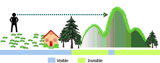
See the figure above, a man is standing at the centroid higher than the lawn, house and woods, so he can see all the spots mentioned. In the figure, the blue part refers the visible extent, green refers the invisible extent. To some locations, they are invisible due to being hidden by the foreground.
In the normal process of overlapping layers, it is impossible to know the visible extent of each point, so there are some blind spots in the plan. If we know the visible extent and what can be seen in a region, the plan can be designed in a way fitting more demands.
See the figure in the upper left side, we know the elevation of the triangulation station but do not know which location is visible for it. See the figure in the upper right side, overlap the layers that is performed with Viewshed analysis, transparency and hillshade analysis with the terrain map, we can realize easily the relationship between the observer point and terrain. |

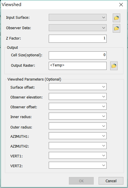
Description of Parameters
Item |
Description |
Data Type |
Input Surface |
The data to perform Viewshed analysis. |
Raster layer |
Observer Data |
The location to observe, the maximum allowable number of points is 16. |
Feature layer(point, line) |
Z Factor |
The default is 1; it means the unit of vertical and horizontal direction are the same. |
Integer/Floating point |
Cell Size |
The cell size of output raster. |
Integer/Floating point |
Output Raster |
The filename and storage path of the output raster(the output can be two kinds of value, 0 and 1. 0 represents invisible area, 1 represents the visible area ). |
Raster layer |
Flexible parameters for visibility:
ViewShed supports multiple parameters such as height observation, angle observation, etc.
Parameters’ setting and explanation are listed below:
Item |
Description |
Surface offset |
This parameter, whose default value is 0, is used to set the elevation value adding on the height value of the observation point. Let’s give an example: This parameter can be applied to specify the height of the observation point surrounded by woods while conducting viewshed analysis. If the height of woods surrounding the observation point is 1 meter; users have to set a value of surface offset as 1m. And then viewshed analysis will be conducted based on the height value and surface offset value and the height value. Finally, the surface will be 1 meter higher than the input surface. |
Observer elevation |
This parameter is used to set height of an observation point. The default value of the observation point is the height value detected from the DTM. |
Observer offset |
This parameter is used to set height of an observation location. Users can apply this parameter to set height of the observation locations such as stations, buildings. The default value is 0. |
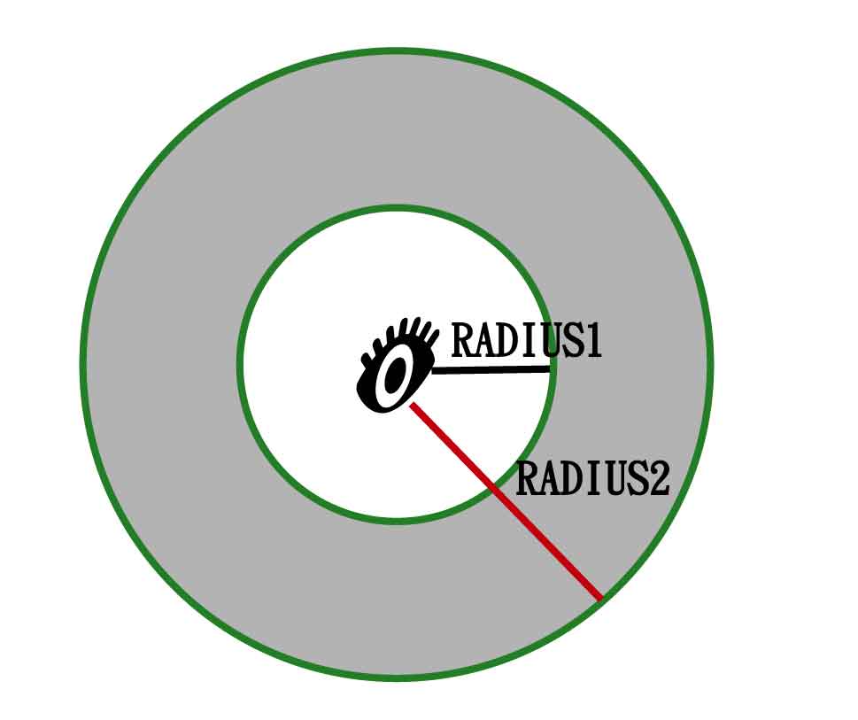
Inner radius |
The parameter, inner radius, defines the start distance of visible range. Cells closer than the inner radius are invisible in the output but considered in the analyst. The gray part in the figure below shows the visible range. The inner radius and outer radius help users define a visual range and make analyst result more realistic to the real world.
|
Outer radius |
This value specifies the maximum distance of visible range. Cells beyond the outer radius are excluded from the analysis. The default value is infinite; you can select a field to specify different values for each observer or assign a value to all. |
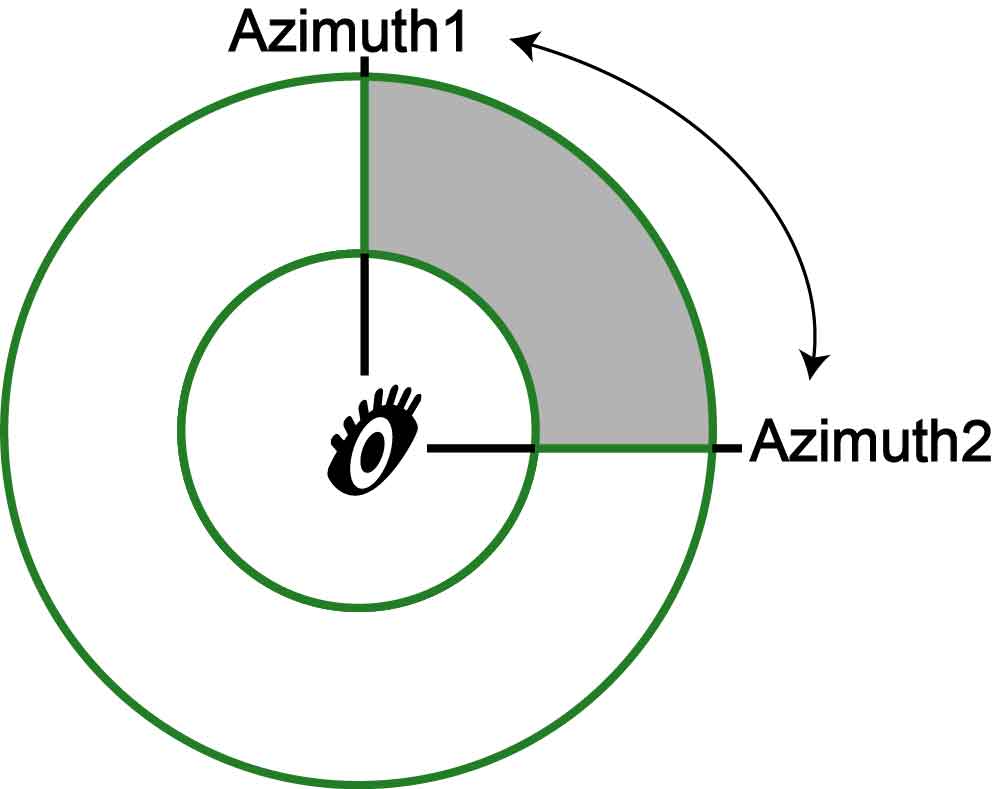
AZIMUTH1 |
Horizontal field of view 1 (Horizontal FOV 1), whose default value is 0 degree. |
AZIMUTH2 |
Horizontal field of view (Horizontal FOV 2), whose default value is 360 degree. To get the horizontal vision angle of observation location, please subtract value of AZIMUTH1from value of AZUMUTH2 by setting the two parameters. You can refer to the figure below: |
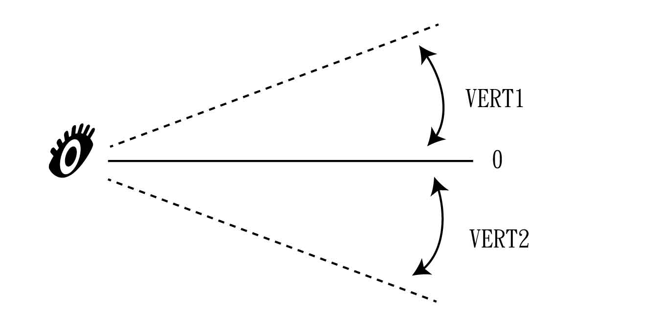
VERT1 |
The vertical field of view (Vertical FOV 1) whose degree is defined from the observation location to the upper horizontal plane. The default degree is 90 degree. |
VERT2 |
The vertical field of view 2 (Vertical FOV 2) whose degree is defined from the observation location to the lower horizontal plane. The default degree is -90 degree. The vertical viewshed of observation location contains vision angle of VERT2 and of VERT1.
|
©2016 Supergeo Technologies Inc. All rights reserved.