
Copy Parallel Line
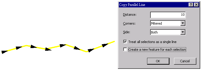
“Copy Parallel Line” is to offset the selected line to its two sides at the specific position to create new features that parallel to it and then save to target layer. To use “Copy Parallel Line”, you need to select more than one line feature, from different layer is acceptable. Select a polyline feature and click the tool, the “Copy Parallel Line” window shows up.
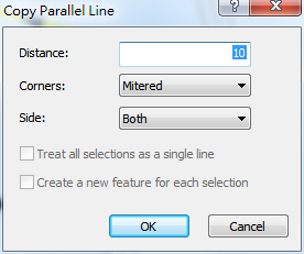
The functions in the “Copy Parallel Line” window:
Distance: the distance between the newly-created parallel line and the original feature, the unit is the same as the map unit.
Corners: it provides three corner types, please see the figure below.
.png)
.png)
.png)
Side: you can decide which side of the selected feature the copied line feature will be drawn; the options include left side, right side and both sides.
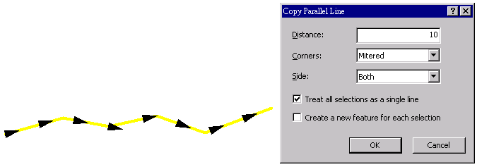
Now we can start to copy parallel line to a single line feature. Select a line feature and click “Copy Parallel Line”, the “Copy Parallel Line” window pops up; in the mean time, the arrows that indicate the direction appear on the selected line feature. The black arrows are used to indicate the digitizing direction of line; once “Copy Parallel Line” window is closed, the arrows will disappear. The generated line feature may not be stored in the source layer but depending on the line layer set in “Target Layer.”
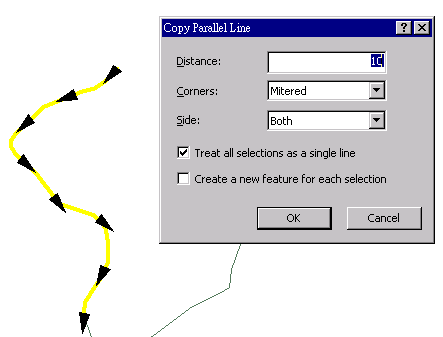
Treat all selections as a single line: it only works when more than two line features are selected (from different layer is acceptable), and they must connect. Please see the figure below.
![]()
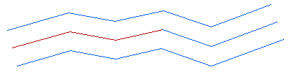
This function is checked by default, but now we will describe the condition if this function is unchecked. If this function is unchecked, and the situation is like multiple line features connect but have different directions, the copied lines will be generated separately without considering the direction and connection problems, please see the figure below.

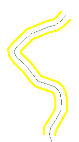
If the item is checked, the direction of all line features must be identical. How to decide the direction? If the line features are in the same layer, the feature with minimum ID number will be the standard; if in different layer, the feature that displays on the top layer will be the standard. In this example, the direction of the feature in right side is adjusted to be identical to the one in the left side, and the generated layer is treated as the result of manipulation with a single one selected feature, please see the figure below.
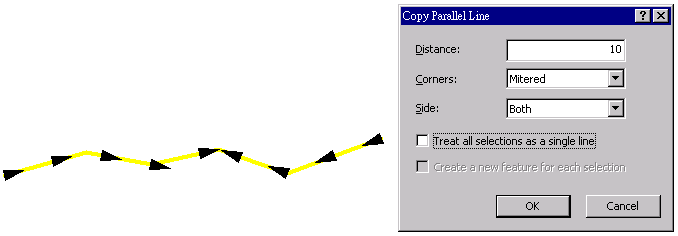
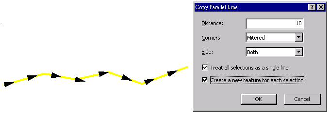
Create a new feature for each selection: it will be disabled, if “Treat all selections as a single line” is unchecked. The default is unchecked; if it is checked, it means though the multiple selected line features are treated as a single line, the lines that are generated will be separated into different features.
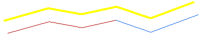
The figure below is the result when “Create new feature for each selection” is checked. Each selected line will create a new feature, so the generated line feature (the blue line in the upper part) will be separated into two line features.
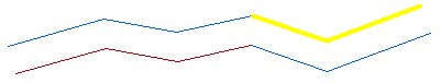
If “Create new feature for each selection” is unchecked, the generated line will be considered as a single line.
©2015 Supergeo Technologies Inc. All rights reserved.