
Introduction to right-click menu
In sketching polyline and polygon features, whether the mouse cursor is on a vertex or not will make the right-click menu different. In other words, the contents of the right-click menu depend on the position of the mouse cursor. Therefore, the commands in the menus will be introduced respectively.
Mouse cursor NOT on a Vertex
Stream Mode: After clicking the command, you can hold the mouse left button and drag a line segment with multiple vertices, rather than sketch point features repeatedly.
Snap to: Move mouse to “Snap to” and it shows four snapping target items: vertex, edge, midpoint, endpoint. This function is able to specify the current vertex to snap to your target, preventing from snapping to wrong target due to over-crowded features.
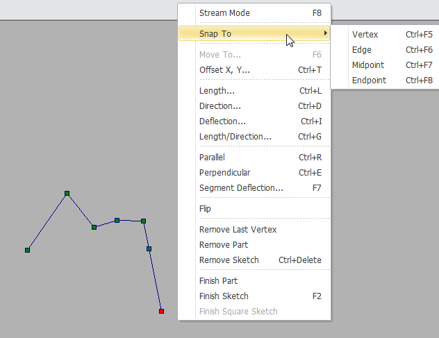
NOTE: This function is irrelevant to layer's snap settings in “Snap Setting” window but it applies the “Tolerance” setting.
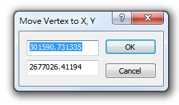
Move To: You can enter the x, y coordinates in the "Move Vertex to X,Y" window. Click "OK", and the system will create a vertex on the new coordinates. The default value in the window is the coordinates of the last right-click.
Offset X, Y: According to the X,Y coordinates you enter in the window, the system will create a new vertex on the relative location. The default x,y values are the relative coordinates between the last right-click and the last vertex.
_new.png)
Length: The distance you enter in the window is the fixed distance between the mouse cursor and the last vertex. The last vertex can be seen as the center of the circle, and the Input Distance is the radius. Then, you can create a new vertex on the circumference. The unit of the distance is map unit. The default value of the distance is the length between the last vertex and the last right-click.
_new.png)
Direction: The angle you enter in the window indicates the direction the new vertex can be added. The system will regard the last vertex as the datum point and see the angle you set as the direction to drag the line segment. With the setting, you can only adjust the length, but not the direction. The default angle is the angle between the last vertex and the last right-click.
_new.png)
In the direction setting, the last vertex is the datum point; 0 degree is north to the last vertex. Positive values are clockwise, so 90 degree is east to the last vertex and 180 degree is south to the last vertex. As the angle is set, the mouse can be only moved by the direction of the angle or the supplementary angle. Then, users can modify the length only but cannot change the direction.
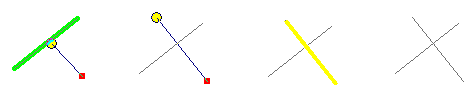
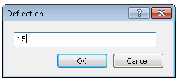
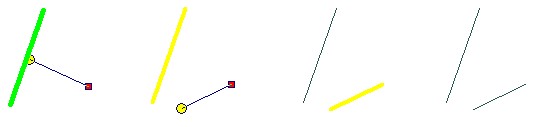
Deflection: The last line segment is the datum of the deflection angle which determines the direction you can sketch. Then, you can change the length only. The default value in Input Deflection Angle is the angle between the last right-click and the last line segment.
_new.png)
Length/Direction: In the window, you can enter the length and the angle, and a new vertex will be created based on you setting. The method to set the length and the direction is the same as the methods described above. The default value is the length and the angle between the last vertex and the last right-click.
_new.png)
Parallel: Click to create the first vertex of the polyline feature, and then move the mouse cursor over the line segment the polyline feature needs to paralyze. Then, right-click it and click "Parallel." The paralyzed line segment will blink. Afterward, you can sketch a line paralyzing the line segment.
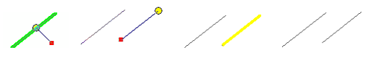
Perpendicular: The operation of the function is similar to "Parallel."
Segment Deflection: The manipulation is similar to “Parallel” and “Perpendicular”, right-click mouse and select this function, a “Input Deflection Angle” window shows up, enter the deflection angle and the segment will deflect according to the angle of the selected feature plus the value you just input.
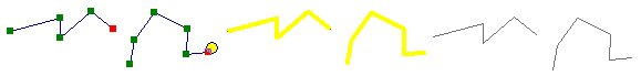
Flip: Click the function, and the direction of the sketch will be reversed. Then you can continue sketch from the first vertex. Thus, this tool can be applied to adjust the direction of the polyline features.
Remove Last Vertex: Click the command, and the last vertex is removed.
Remove Part: Click the command, the part you are sketching is removed.
Remove Sketch: This command is to remove the feature you are sketching.
NOTE: The functions of "Remove Part" and "Remove Sketch" are the same as you are sketching a single feature.
Finish Part: Click the function, the current part can be finished. And you can continue to sketch another part of the feature. Sketching with the tool, you can multiple parts belonging to one feature.
Finish Sketch: Click the command to finish sketch.
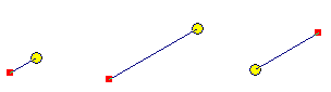
Finish square sketch: It can be applied to polygon layer. When at least 3 vertices have been digitized, this function will help you add the last vertex automatically and complete a polygon. Two segments will be added at right angle to connect the last vertex and the existing vertices. The function will facilitate users to digitize rectangle, which can work with “Offset” to accomplish the creation of rectangle feature.
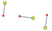
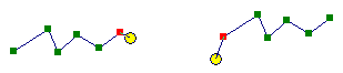
After at least three vertices are digitized, use “Finish Square Sketch.”
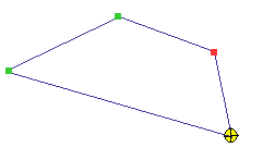
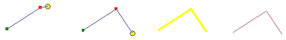
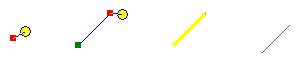
The system will find the extended line that extends through the first vertex and perpendicular to the first segment as well as the one that extends through the last vertex and perpendicular to the last segment. The intersection of the two extended lines will be added with a vertex by the system automatically (the yellow cursor in the left figure). However, if the two extended lines are parallel, “Finish square sketch” is invalid.
.png)
.png)
NOTE: “Finish square sketch” is mainly for digitizing polygon, but it cannot work until at least three vertices are digitized.
NOTE: When using the right-click menu functions mentioned above, if you are editing a line feature, the status bar at the lower left corner in the window will show some information based on the current cursor's location
![]() . If you are editing a polygon feature, it shows
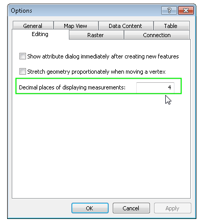
. If you are editing a polygon feature, it shows ![]() . Users can get information of the editing feature from the status bar when digitizing vertex. In addition, the decimal place of the value in status bar can be decided in “Decimal places of displaying measurements” in “Tools”>“Options” >“Editing” tab.
. Users can get information of the editing feature from the status bar when digitizing vertex. In addition, the decimal place of the value in status bar can be decided in “Decimal places of displaying measurements” in “Tools”>“Options” >“Editing” tab.
©2015 Supergeo Technologies Inc. All rights reserved.